Monday, May 4, 2020

Arduino LED Light strip | PHASE 2

Arduino LED Light strip | PHASE 2

Hey! Welcome back. Here is the next part where I continue to stumble my way through my first LED light project.

The trial run I did in part 1 proved a couple things.

  1. It told me that it could be done!
  2. There were a couple issues I needed to sort out before phase 2.
  3. I didn't need to break the piggy bank to make something awesome.

One issue I had to overcome was getting the command to the Arduino. In the previous section I had just resulted to reprogramming the Arduino every time I wanted the lights to change. This method comes with a couple issues.
  1. The transition between light schemes is pretty choppy and noticeably clunky.
  2. Reprogramming a device is not an elegant solution and reduces the device's life span.
I'm not sure if the second item above is actually true but never the less I didn't like reprogramming the device that often. So, I came up with a solution that could be seen as pointless and possibly overkill for what I wanted to do. ¯\_(ツ)_/¯ But i'm me and if a solution isn't necessary but IS either more awesome and/or abides to the rule of cool then I want to do it. Having a lighting solution that can respond to my will definitely falls into the awesome/cool category.


Since the Arduino was already connected via USB connection I thought that utilizing this connection could be a good method for sending commands to the Arduino. I learned a few things.

WARNING! TECHNICAL BITS AND ISSUES ENCOUNTERED TO FOLLOW!


Scroll to the bottom if you're just looking for the pretty pictures from the project.
People Posts GIF - Find & Share on GIPHY

The way I was going to communicate to the Arduino was over a USB connection using something called a serial connection. The serial connection protocol is a little tricky to use because the data is passed to and from the device is in a raw unprocessed format. It is also sent at a rate measured by something called "baud". This rate is cleverly named "baud" rate.

I didn't name it.
John Travolta Bolo Tie GIF - Find & Share on GIPHY

One downfall of this system is that if the baud rate on the receiving device does not match the baud rate of the sending device then the data will appear as garbage. Meaning the device doing the interpreting of said data won't be able to make any sense of it.

It's a lot like this.
GOLDEN GIRL — sparklejamesysparkle: Lucille Ball as a hapless...

Its like if an English speaking person understood English but only if the English being spoken was spoken backwards. Its still technically English but can't be understood because English spoken backwards sounds completely different than regular English not spoken backwards. Some might call this magic.

For example: Computer A sends the word "hello" via USB serial connection at a baud rate of 14400 to an Arduino. The Arduino receives data over USB serial connection at a baud rate of 9600. The Arduino receives the information but cannot see the word "hello" as intended by computer A. The Arduino can still understand that "Yes, this is text that I'm receiving!" but when it goes to interpret the text it instead sees a mishmash-ed random jumble of characters. Much like the backwards English example, the Arduino can't make sense of the received data.

!Read sculpture below
Cleaning up mistranslated signs - What a cool idea - Translation ...

The Arduino would need to know that the data being received from Computer A is to be interpreted in a certain way so that the commands can be understood.

This... took awhile. Collectively we're talking a couple days to figure out a good program algorithm that would allow the Arduino to function in the way that we wanted. It took awhile to get certain information because most people online prefer to tell why your method is wrong, or why it won't work instead of just answering the specific question you're asking.

Additionally, during this period I may have accidentally overwritten part of the code I had recently spent hours working on JUST as it started working the way I wanted.

Nuclear Explosion GIF - Find & Share on GIPHY

And finally the issue that was probably the most annoying to overcome was an issue that crept up after the code was working correctly. At some point the serial connection just... stopped receiving anything useful. At all. The Arduino just reported receiving nothing. Super. What time is it? 2:00 am? Wonderful. Well, it turns out the serial connections utilize something called a buffer. And if it gets full it stops working. So that was fun to work through...

Have you ever wondered why highly technical people some times act so strange? This is why. Its all just a weird variant of PTSD.

Almost
Gene Wilder Frankenstein GIF by foxhorror - Find & Share on GIPHY

Okay, sorry. Frenetic ranting over. The new LED strip arrived and there was much rejoicing! As before I wanted to see what this strip was capable of vs. the $5 one from the store. Following a tutorial I found online I hooked up the Arduino to the light strip, imported a control library and reprogrammed the Arduino. This is what happened.


Holy smokes it can MOVE! Excellent. Immediately went and ordered more LEDs. 16 feet to be exact. One of the main upsides to these light strips over the Phase 1 strips is that each individual light can be programmed to do specific things including light intensity, blinking, color, etc.

I also bought an LED strip extension kit that came with 9 feet of extra wire and 7 clamps that made increasing the covered area much easier. For the serial communications I'm using a Raspberry PI mini computer connected via an X10 ethernet connection that eliminates the need for having any cords run over the main floor area.


For the 3 foot LED light strip that I ordered first to use for testing I needed something that would reliably hold it in place that I could mount under the desk. Turns out! I had a spare broom that I never used and figured the handle would get more use if I strapped some lights to it and shoved it under a desk.
It looks like this.


The complete Arduino LED Light Strip project!
Note that most of these pictures look very similar to Phase 1 and... That's on purpose. Phase 2 was just a better higher quality implementation of Phase 1.


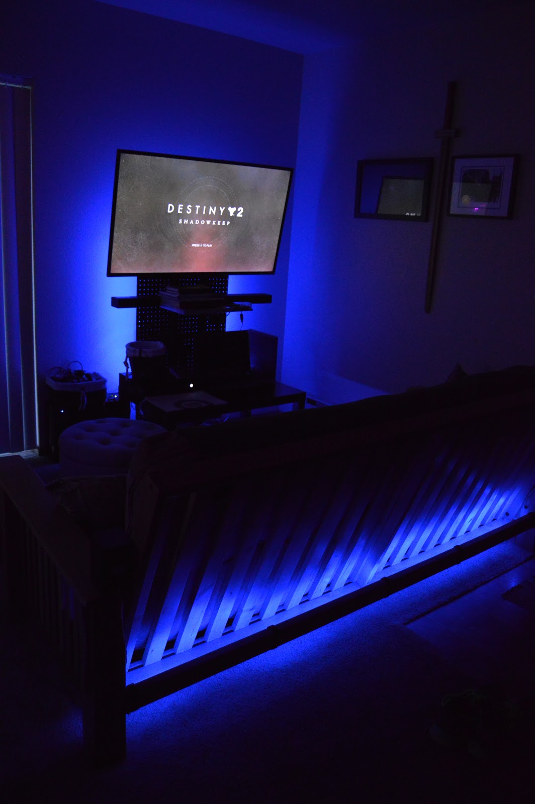
I don't have an HD video camera so these are a little... Non HD.

Arduino LED controller | PHASE 1 COMPLETE!

PHASE 1 PROGRESS!

Continued from Part 1
Checkout Part 2

I'll be honest I got bored waiting for the LED light strip to arrive so I went to my local Walmart to see what kind of LED light strip related items they had. To my surprise they had a couple LED strips for ~$5 each. Being a man of caution I bought two of them, sped home locked the doors and shut the blinds. I found a USB phone charger and connected the thing using a connector that came with the light strip. For $5 they immediately exceeded my expectations.

Hey look! Lights!

Hooking the LED light strip up to one of the Arduino controllers worked very well and was easier than I expected.

Perfect! Being able to control the LEDs with the Arduino controller means that we can proceed with  positioning the lights in such a way that gives the room a nice RGB glow that we can control with the Arduino. After deciding on a layout I then had to figure out how I was going to control the lights.

Making the Arduino control the LED strip would be done via an arduino sketch. This sketch will essentially evaluate a word and match it to an appropriate action. This conceptually will allow the LED light strip to respond to what we tell it.

Links to the Github where the code for this stage lives is below:
https://github.com/superconfused1/Arduino-Light-Control

Here is what Phase 1 looks like after it is all completed using the $5 LED strip from the store!


Tuesday, April 21, 2020

Arduino LED controller | PHASE 1

5/4 UPDATE: Phase 1 complete
Checkout Part 2

Hey! Listen, sorry. I've been a little busy.

(To date this post) With all the COVID quarantine shenanigans I was feeling a little depressed from being locked in my dark apartment all day... and as my introverted friends know all to well, the darkness does things to you. Things that I wasn't able to stave off with just my normal 7.5 mile 3x a week run (I might be a little crazy)!

To combat this, my brain dug up memories of super awesome LED lighting I saw on Pinterest.

PHASE 1

NOTE:
If you're here only for the schematics... They're not here yet. 😊 But might end up here if I remember to come back and add them! May the odds be ever in your favor.

Woa, look! Examples:
(All rights go to where ever I got this from. 😄 THESE ARE NOT MINE!)
That should cover it, right?

Yeah, pretty...


Yeah!


YEAH


YEAH!!!


Alright, after I've inceptioned myself with this super awesome idea I set off doing what I do: researching the most cost efficient, awesome and Bryan way to do things.

Sure, I could just buy a pre-made solution and then...


NO! There is no room for boring here.

The first option I thought of was making a Christmas YouTube style light show like the one below.
Christmas Lights GIF - Find & Share on GIPHY
#WizardsInWinter

But! Instead of Christmas music and flashing lights it would just be solid colors... and no music... I'd essentially be making a really boring Christmas lights display which seems like a lot of work for a fairly limited audience and I'm lazy. However, it wasn't off the table yet. To quote a favorite video game of mine: "Additional research is required."

WARNING! INFORMATIVE SECTION BELOW!
The way those fancy Christmas light displays work is that most of them use strands of  LED lights that are all connected to a lighting controller. Cleverly named, right? Don't blame me, that's what I found during my research. Probably named by an engineer or something. "What does this thing do?" "It controls lights." "Ah, well that there is a lighting controller." "Excellent! You get a raise."

These lighting controllers are (essentially) the same systems that professional performance and stage technicians use to make light shows for concerts, church services and the rave in John Wick with varying levels of sophistication, quality and price.

At this point there were two options that seemed reasonable to me, a lowely IT Technician/hobbyist of cool things.
1) The DIY (do it yourself) option
2) Purchasing a low level product that still allowed me to pay rent this month

The DIY option:
This first one I found was the Build-It-Yourself kit from a company called Light-O-Rama.
http://www1.lightorama.com/build-it-yourself-kits/

It turns out that the light controller business is a pretty big industry and this one seemed pretty good until I saw that the entire system needed assembly.

Don't get me wrong I love a building project but at this point I just wanted to see if it was a feasible idea. This kit also cost$131.95.

Yes, there are other DIY projects out there which could be more suitable but this gave me a sense of scale for the amount of work that would go into this.

Look at all those breakable/lose-able pieces!
Hendrix Family Holiday Light Show - Publicaciones | Facebook


The pre-built "purchase a thing" option:
This... proved a lot more difficult than I expected. The simple human part of me expected to search Amazon and Google for "lighting controller" and be greeted with a multitude of useful results. Not exactly what happened for me. A main issue was that I didn't really know what to search for. The results I found included professional grade AC lighting controllers, computer case LED controllers, and home automation lighting controllers. While not wrong they still didn't seem like what I was looking for.

I figured I must be asking wrong question.
Ask Questions GIF - Find & Share on GIPHY

I went back to the Google and began combing the web. It seemed like I would have to re-think my initial plan for implementing an LED lighting display in a way that wouldn't take all year to complete as well as not being crap at the end. And then I stumbled across something interesting.

During my searching I kept seeing different combinations of the terms "Arduino" and "Individually Addressable RGB LED light strips". Specifically, the WS2812B style of LED strip seen below.


This got the wheels in my head to start turning. I was familiar with Arduino devices but not so much with the LED light strips. An Arduino is a little device classed as a micro-controller. In normal human speak, its a device you program for a few specific purposes.

Some look like this!


Okay... But how easy straightforward is hooking an LED light strip up to one of these guys and then programming it to bend it to my will? Lets run through it.

The Arduino can be programmed via an IDE (Integrated Development Environment or a program that lets you work on code) once it is connected to a computer via a USB connection. It doesn't necessarily need the computer connection once its programmed. All it requires is a 5v power source which is what most standard USB connectors like phone chargers and wall sockets provide. The programming language is C/C++ which is perfect since I recently took some classes on both of those languages and know enough to know when I'm about to be dangerous!

So, we can power the thing, and we can program the thing. What about connecting the thing to the other thing?

I did some more looking around and found a pretty helpful video about how to connect the LED strip to the Arduino and realized that its pretty simple. All you need to do is connect the 3 contact points on the LED strip to three corresponding pins on the Arduino and it should theoretically just work. Maybe. A game/software tester's most hated combination of words.

The video! (Again. It's not mine):
BEGINNERS Guide to Individually Addressable RGB LED Programming with Arduino
https://www.youtube.com/watch?v=WS6FI_NyRzs

Wiring diagram from the same video:


Cool! Seems simple enough and I've got the materials to get started! I had an Arduino starter kit I bought when I was bored a few years back and never used it. The kit had an assortment of LEDs, motors, resistors and an Arduino. Only thing I do not have is my own LED light strip.

Fortunately, Amazon was able to help me out with a 3 foot LED strip that I could start with and not have 100's of feet of LED lighting laying around my apartment if it didn't work. (I know there are smaller lengths like 16 feet and such, but 100 feet sounded better.)

The strip:
https://www.amazon.com/gp/product/B01CDTEFAQ

While waiting for the part to be delivered I figured I'd get my feet wet working with the Arduino and programming the little thing. I run Debian 9 on the PC I'll be using to program it and got the Arduino 1.8.12 IDE installed. The IDE actually started communicating with the Arduino immediately after hooking it up to the computer. Neat! Easy! After applying my C++ coding knowledge and peaking at an example or two I was able to get a full program (Arduino calls them sketches) to successfully compile.

The first two iterations of the sketch involved a single LED and then a single LED blinking! That is a degree of success! However, I am a man and I was not done yet and after finding a second Arduino (and staring at it for a second because I'm not... quite sure where it came from) decided to opt into the "be awesome" option.

The end result is two Arduino micro-controllers powering 5 LEDs each. The LEDs light up in a sort of... I don't know, back and forth motion? I'm sure there is a technical term for it.

See it below!

It also looks pretty cool at night.

Now, I know what you're thinking that this is just an unimpressive messy jumble of useless lights and seizure inducing colors! And you're right! You are also very harsh and demanding. Fortunately, this was just phase one! Once the LED light strip comes in next week (4/28-ish) I'll be able to start messing around with getting a really neat light display going and then integrating it into Wednesday's control system.

Well, that's all until the LED strip comes in I guess. L8ers!!!

Q. "Who is Wednesday?"
A. Oh, Wednesday is my home automation system/AI I'm building. I'll introduce you later. 😄

Q. "Why did you name it Wednesday?"
A. I said I'll introduce you later!!!

Q. "Is it really an AI?"
A. Go away.


-Bryan

5/4 UPDATE: Phase 1 complete